 |
The theory of elasticity
is quite difficult just for simple homogeneous media (no crystal), and even more difficult for crystals with dislocations
- because the dislocation core cannot be treated with the linear approximations always used when the math gets tough.
|
|
 |
Moreover, relatively simple analytical solutions
for e.g. the elastic energy stored in the displacement field of a dislocation, are only obtained for an infinite
crystal, but then often lead to infinities. |
|
|
As an example, the energy of one dislocation in an otherwise
perfect infinite crystal comes out to be infinite! |
|
This looks not very promising. However, for practical
purposes, very simple relations can be obtained in good approximations. |
|
|
This is especially true for the energy per unit length,
the line energy of a dislocation, and for the forces between dislocations, or between dislocations
and other defects. |
|
A very good introduction into the elasticity theory as applied to dislocation
is given in the text book Introduction to Dislocations of D. Hull and D. J. Bacon.
We will essentially follow the presentation in this book. |
|
The atoms in a crystal containing a dislocation are displaced from their perfect
lattice sites, and the resulting distortion produces a displacement field in the crystal around the dislocation. |
|
|
If there is a displacement field, we automatically have a stress field and a
strain field, too. Try not to mix up displacement, stress and strain! |
|
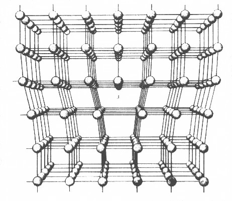
If we look at the picture of the edge
dislocation, we see that the region above the inserted half-plane is in compression
- the distance between the atoms is smaller then in equilibrium; the region below the half-plane is in tension. |
|
|
The dislocation is therefore a source of internal stress in the crystal.
In all regions of the crystal except right at the dislocation core, the stress is small enough to be treated by conventional
linear elasticity theory. Moreover, it is generally sufficient to use isotropic
theory, simplifying things even more. |
|
|
If we know what is called the elastic field, i.e. the
relative displacement of all atoms, we can calculate the force that a dislocation exerts
on other dislocations, or, more generally, any interaction with elastic fields from other defects or from external forces.
We also can then calculate the energy contained in the elastic field produced by a dislocation. |
|
|
|
The first element of elasticity theory is to define the displacement field
u(x,y,z), where u is a vector that defines the displacement of atoms or,
since we essentially consider a continuum, the displacement of any point P in a strained body from its original (unstrained)
position to the position P' in the strained state. |
|
|
|
|
 |
Displacement of P to P'
by displacement vector u |
|
|
The displacement vector u(x, y, z) is then given by |
| |
| u(x, y, z) | = | ux(x, y, z)
uy(x, y, z)
uz(x, y, z)] |
|
|
| |
|
|
The components ux , uy
, uz represent projections of u on the x, y,
z axes, as shown above. |
|
The vector field u, however, contains not only uninteresting rigid body
translations, but at some point (x,y,z) all the summed up displacements from the other parts of the body.
|
|
|
If, for example, a long rod is just elongated along the x-axis,
the resulting u field, if we neglect the contraction, would be |
| |
| ux | = |
const · x | |
uy | = | 0 |
| uz |
= | 0 |
|
|
|
|
But we are only interested in the local deformation, i.e.
the deformation that acts on a volume element dV
after it has been displaced some amount defined by the environment. In other words,
we only are interested in the changes of the shape of a volume element that was a perfect
cube in the undisplaced state. In the example above, all volume element cubes would
deform into a rectangular block. |
|
We thus resort to the local strain
e, defined
by the nine components of the strain tensor acting on an elementary cube. That this is true for small strains you can prove
for yourself in the next exercise. |
|
|
Applied to our case, the nine components of the strain
tensor are directly given in terms of the first derivatives of the displacement components.
If you are not sure about this, activate the link. |
|
|
We obtain the normal strain as the diagonal elements of
the strain tensor. |
| |
| exx | = |
dux
dx | |
eyy | = |
duy
dy | |
ezz | = |
duz
dz |
|
|
|
|
The shear strains are contained in the rest of the tensor:
|
| |
| eyz | = |
ezy | = | ½ · |
æ
è |
duy
dz | + |
duz
dy | ö
ø
|
| ezx | = |
exz | = | ½ · |
æ
è |
duz
dx | + |
dux
dz | ö
ø
|
| exy | = |
eyx | = | ½ · |
æ
è |
dux
dy | + |
duy
dx | ö
ø
|
|
|
|
Within our basic assumption of linear theory, the magnitude of these components
is << 1. The normal strains simply represent the fractional change in length of elements parallel to the x,
y, and z axes respectively. The physical meaning of the shear strains is shown in the following
illustration |
| |
|
|
|
A small area element ABCD in the xy plane has been strained to
the shape A B' C' D' without change of area. The angle between the sides AB and AD,
initially parallel to x and y, respectively, has decreased by 2exy.
By rotating, but not deforming, the element as shown on the right-hand side, it is seen that the element has undergone a
simple shear. The simple shear strain often used in engineering practice is 2exy,
as indicated. |
|
|
The volume V of a small volume element is changed by strain to |
| |
| V + DV | = |
V · (1 + exx ) · (1 + eyy)
· (1 + ezz) |
|
|
|
|
The fractional change in volume D, known as the dilatation, is therefore |
|
|
| D | = |
DV
V |
= exx + eyy + ezz |
|
|
|
|
Note that D is independent of the orientation of the axes
x, y, z |
| | |
|
|
The component sij, where i and j
can be x, y, or z, is defined as the force per unit area exerted in the + i
direction on a face with outward normal in the + j direction by the material outside
upon the material inside. For a face with outward normal in the – j direction,
i.e. the bottom and back faces in the figure above, sij is the force per unit
area exerted in the – i direction. For example, syz acts in the
positive y direction on the top face and the negative y direction on the bottom face. |
|
|
The six components with i unequal to j are the shear
stresses. It is customary to abbreviate shear stresses with t. In dislocation studies
t without an index then often represents the shear stress acting on the slip
plane in the slip direction of a crystal. |
|
|
As mentioned above, by considering moments of forces taken about x, y, and
z axes placed through the centre of the cube, it can be shown that rotational equilibrium of the element,
i.e. net momentum = 0, requires |
|
|
| tzy | =
| tzy | |
tzx | = |
txz |
|
txy | = |
tyx |
|
|
|
|
It therefore does not matter in which order the subscripts are written. |
|
|
The three remaining components sxx, syy,
szz are the normal components of the stress.
From the definition given above, a positive normal stress results in tension,
and a negative one in compression. We can define
an effective pressure acting on a volume element by |
| |
|
|
For some problems, it is more convenient to use cylindrical polar coordinates (r, q, z).
|
|
|
This is shown below; the proper volume element of cylindrical polar coordinates, is essentially
a "piece of cake". |
|
|
|
|
Is it a piece of cake indeed? Well - no! |
|
|
The picture above is straight form the really good book of
Introduction to Dislocations of D. Hull and D. J. Bacon, but it is a little bit wrong. But since it was only used a basic illustration,
it did not produce faulty reasoning or equations. |
|
|
The picture below shows it right - think about it a bit yourself. (Hint: Imagine a situation,
where you apply an uniaxial stress and try to keep your volume element in place) |
| |
|
|
|
The stresses are defined as shown above; the stress sz,
q, e.g., is the stress in z-direction on the q
plane. The second subscript j thus denotes the plane or face of the "slice of cake" volume element that
is perpendicular to the axis denote by the sunscript - as in the cartesian coordinate system above.
The yellow plane or face thus is the q plane, green corresponds to the r
plane and pink denotes the z plane |
|
|
|
In the simplest approximation (which is almost always good enough) the
relation between stress and strain is taken to be linear, as in most "material laws" (take, e.g. "Ohm's law", or the relation between electrical field and polarization
expressed by the dielectric constant); it is called "Hooke's
law". |
|
|
Each strain component is linearly proportional to each stress component; in full generality
for anisotropic media we have, e.g. |
| |
| e11 | = |
a11s11 + a22s22
+ a33s33 + a12s12
+ a13s13 + a23s23 |
|
|
|
|
For symmetry reasons, not all aij are independent; but even in the worst case (i.e. triclinic
lattice) only 21 independent components remain. |
|
|
For isotropic solids, however, only two
independent aij remain and Hooke's law can be written as |
| |
| sxx | = |
2G · exx + l
· (exx + eyy + ezz) |
| syy | = |
2G · eyy + l
· (exx + eyy + ezz) |
| szz | = |
2G · ezz + l
· (exx + eyy + ezz) |
|
|
|
|
The two remaining material parameters l and G are known
as Lamé
constants, but G is more commonly known as the shear modulus. |
|
It is customary to use different elastic moduli, too. But for isotropic cubic
crystals there are always only two independent constants; if you have more, some may
expressed by the other ones. |
|
|
Most frequently used, and most useful
are Young's
modulus, Y , Poisson's
ratio, n, and the bulk modulus, K. These moduli refer to simple
deformation experiments: |
|
|
Under uniaxial, normal loading in the longitudinal direction, Young's modulus
Y equals the ratio of longitudinal stress to longitudinal strain, and Poisson's ratio
n equals the negative ratio of lateral strain to longitudinal strain. The bulk modulus
K is defined to be – p/DV (p = pressure,
DV = volume change). Since only two material parameters are required in Hooke's
law, these constants are interrelated by the following equations |
|
|
|
|
Typical values of Y and n for
metallic and ceramic solids are in the ranges Y = (40-600) GNm–2 and n
= (0.2 – 0.45), respectively. |
|
|
|
A material under strain contains elastic energy - it is just the sum of the energy
it takes to move atoms off their equilibrium position at the bottom of the potential well from the binding potential. Since
energy is the sum over all displacements time the force needed for the displacement, we have: |
|
|
Elastic strain energy
Eel per unit volume = one-half the product of stress times strain for each component. The factor
1/2 comes from counting twice by taking each component. Thus, for an element of volume dV, the elastic
strain energy is |
| |
| dEel | = ½ · |
S
i = x,y,z |
|
S
j = x,y,z |
sij · eij |
· dV |
|
|
|
|
For polar or cylindrical coordinates we would get a similar formula. |
|
We do not actually have to calculate the energy with this formula (be grateful),
but you must remember: If we have the stress field, we can calculate the strain field. If have both, we can calculate the
energy. |
|
|
And if we have the energy we have (almost) everything! Minimizing the energy gives the equilibrium configuration;
gradients of the energy with respect to coordinates give forces, and so on. |
© H. Föll (Defects - Script)


